

Authoring Tutorials
DEP ships three authoring tutorials as bundled projects. Each one contains an editable model source, a prepared executable already placed in the System, and a saved scenario with exact expected values. Run the scenario first to see the tutorial pass, then explore the source and change it.
Open each tutorial from Overview → Projects and save a working copy with File → Save Project As... first. You can edit the sources. Preparing a changed physical or state-logic source into a new executable currently needs DEVlink's development compiler tools. The prepared executables run on any installed DEP. Do not present the old prepared executable as evidence for a modified source.
Physical RC tutorial
Learn: how a conserving electrical network is built, prepared and verified against an analytical solution.
The circuit
A 12 V supply charges a 10 mF capacitor, initially at 0 V, through a 10 Ω series resistor, with an electrical reference (ground). The fixed step is 10 ms. DEP integrates with backward Euler, which gives the capacitor voltage after k steps:
V(k) = 12 × (1 − (1/1.1)^k)        V(10) ≈ 7.37348 V
I_R(k) = (12 − V(k)) / 10           and   C × (V(k) − V(k−1)) / dt = I_R(k)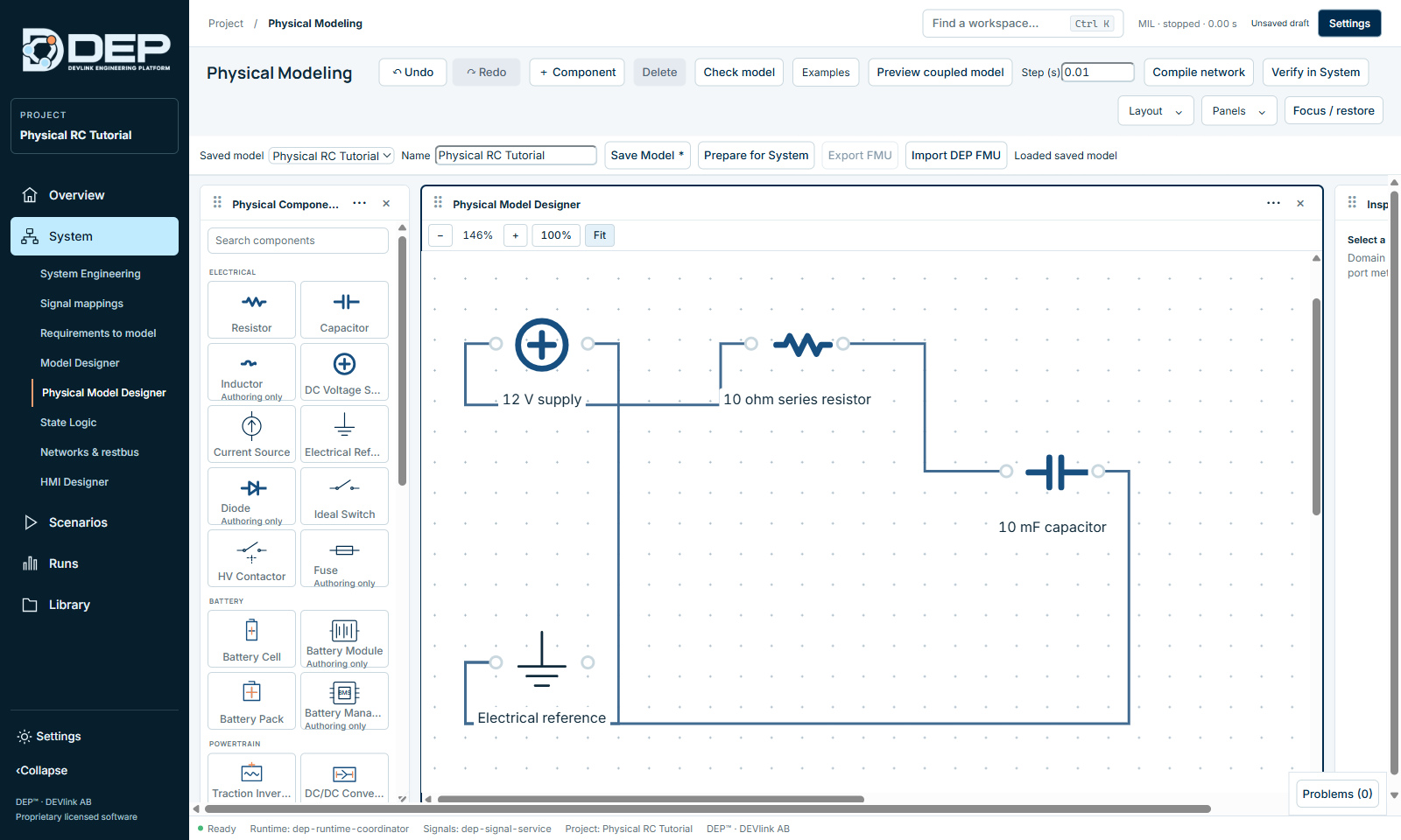
Steps
- OpenOpen Physical RC Tutorial, then Open System. The prepared circuit is already attached as one MIL component.
- Inspect the sourceOpen System → Physical Model Designer and choose Physical RC Tutorial in Saved model. Check the wires and the capacitor's initial condition.
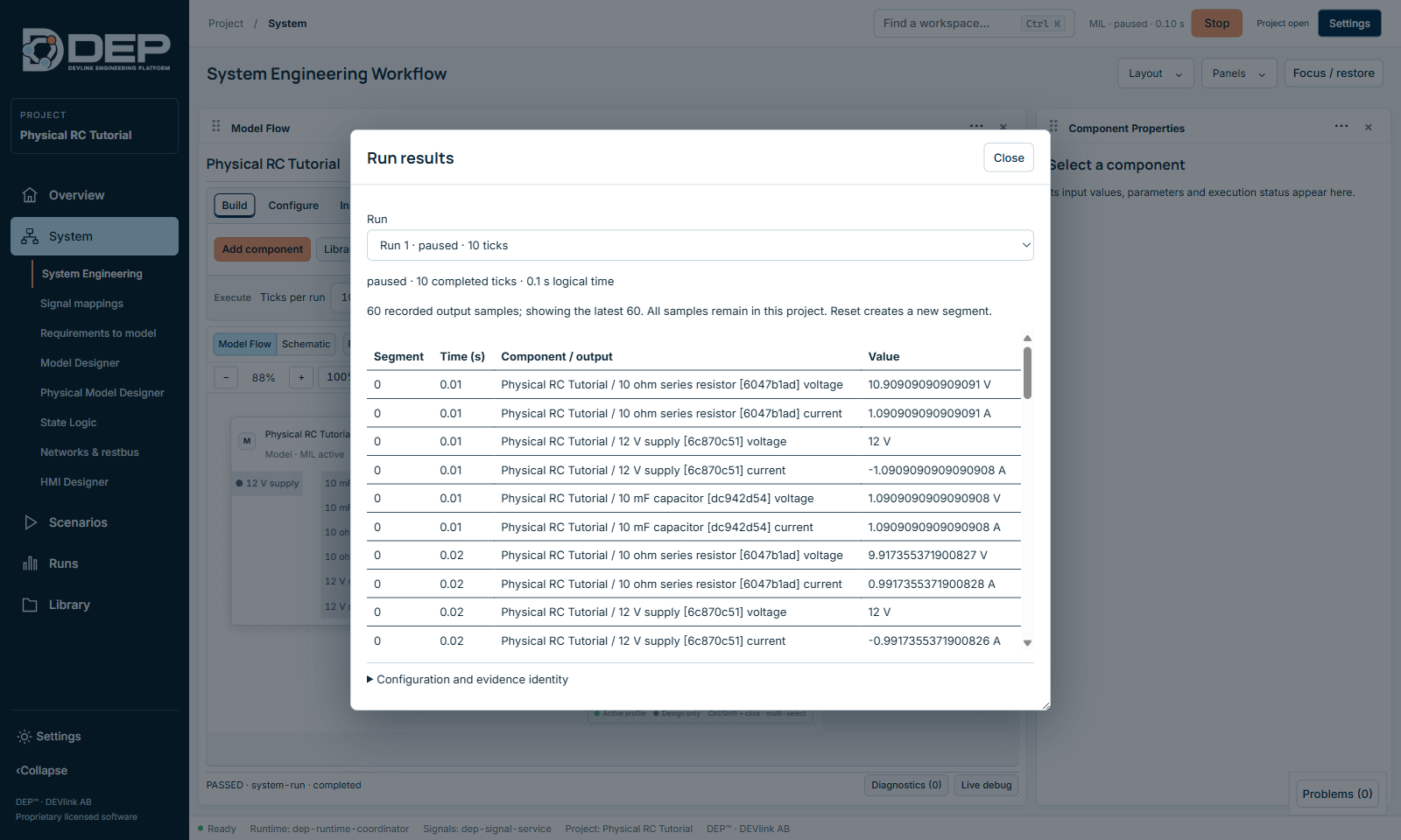
- Run 10 ticksBack in System Engineering, set Ticks per run to 10, select Check and then Run.
- Read the resultsResults lists, for every tick, the voltage and current of the supply, the resistor and the capacitor. The first tick shows the capacitor at 1.0909 V with 1.0909 A, and the resistor at 10.909 V. Tick 10 shows about 7.37348 V across the capacitor.
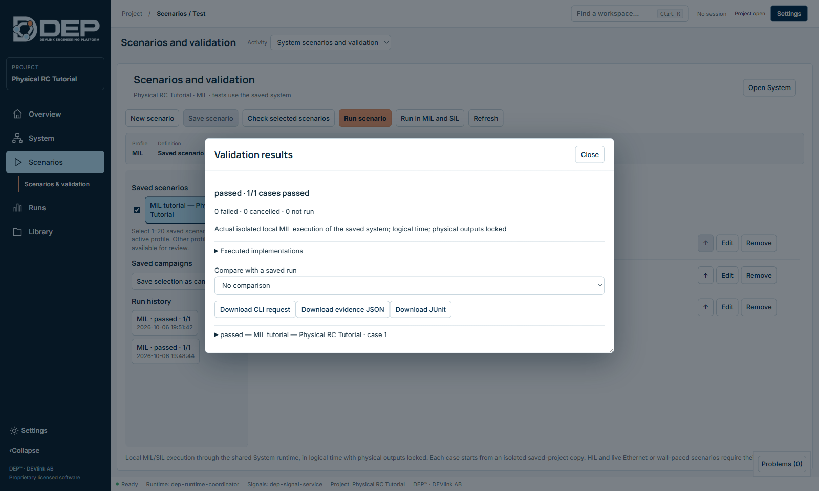
- Run the saved scenarioIn Scenarios & validation, select MIL tutorial — Physical RC Tutorial, tick it and select Run scenario. It sets the supply to 12 V, runs 10 ticks and checks capacitor voltage == 7.37348052684562 ± 1e-8. The result is passed · 1/1.
- Check resetReset must restore 0 V on the capacitor. Run again and compare.
State supervisor tutorial
Learn: states, transitions with priorities, a latched fault and reset rules, and how to test sequential behaviour with a scenario.
The machine
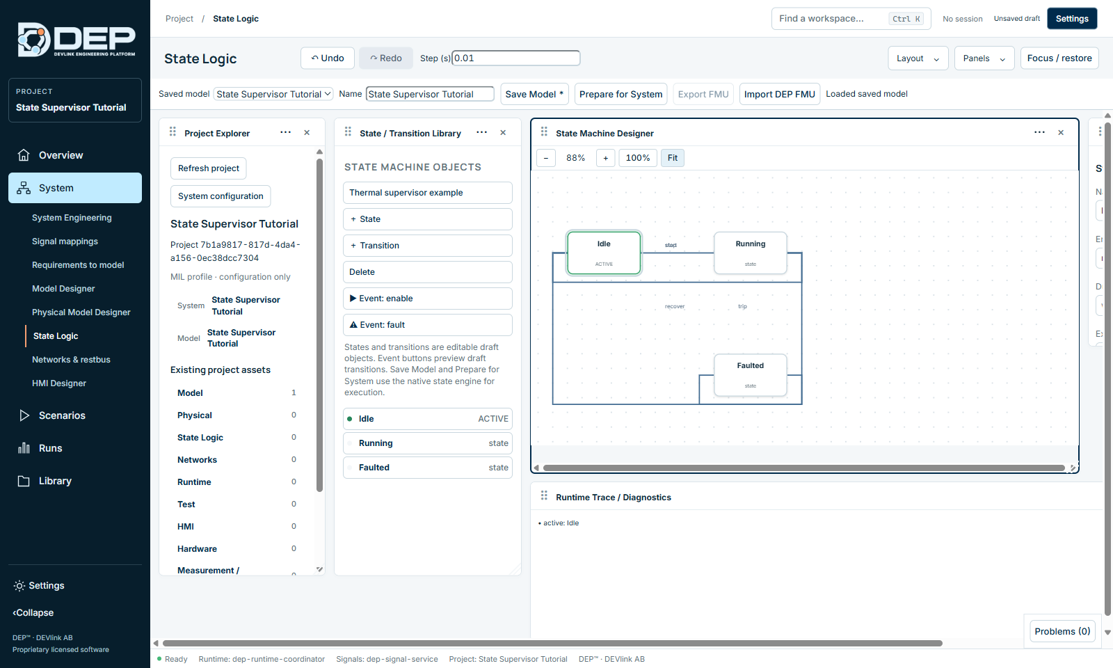
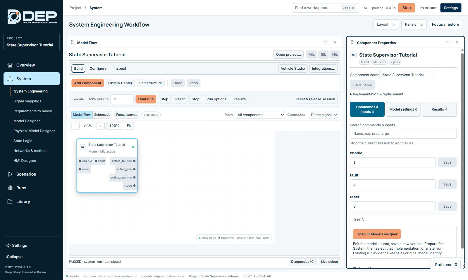
Three states: Idle, Running and Faulted. Three inputs: enable, fault and reset. One output, mode: 0 = Idle, 1 = Running, 2 = Faulted. The outputs active_idle, active_running and active_faulted show the active state. The transitions are start (Idle → Running), stop (Running → Idle), trip (→ Faulted) and recover (Faulted → Idle). Fault transitions take priority over ordinary stop transitions.
Expected behaviour
| Inputs | After one tick |
|---|---|
| enable = 1 | mode = 1 (Running) |
| fault = 1 | mode = 2 (Faulted) |
| fault = 0, without reset | mode stays 2: the fault is latched |
| reset = 1 while enable is still 1 | mode stays 2: reset does not clear the fault while enabled |
| enable = 0 and reset = 1 | mode = 0 (Idle) |
Steps
- OpenOpen State Supervisor Tutorial and inspect the source in System → State Logic, choosing State Supervisor Tutorial in Saved model.
- Try it by handIn System Engineering, select the component and set enable = 1 in Commands & inputs. Set Ticks per run to 1 and select Run. Results in Component Properties shows mode = 1 and active_running = 1.
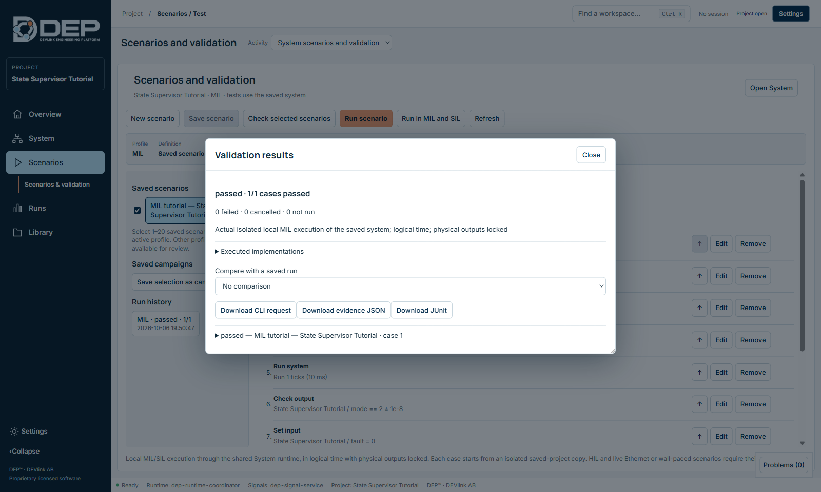
- Run the saved scenarioInputs can only be changed between sessions, and releasing a session resets the machine. Sequences that depend on earlier ticks are therefore best tested with a scenario. Run MIL tutorial — State Supervisor Tutorial. In one case it sets enable = 1 and checks mode = 1, sets fault = 1 and checks mode = 2, then clears fault, sets enable = 0 and reset = 1 and checks mode = 0. It passes. Add steps for the latch and reset-while-enabled rows to extend it.
The supervisor is an illustrative example, not a safety-certified controller.
CoPilot battery tutorial
Learn: the requirements-to-model workflow, from requirements to a reviewed specification and a generated, editable native model. No cloud AI service is needed for this deterministic battery generation.
The requirements
| ID | Requirement (summary) |
|---|---|
| BAT-ELECTRICAL | Twelve series cells with individual SOC, a reviewed OCV curve and internal resistance. Positive pack current discharges. Common current is limited by cell charge, voltage and temperature bounds. |
| BAT-BALANCE | When enabled, shunt cells whose OCV exceeds the minimum cell OCV by the reviewed delta, respecting minimum SOC, temperature, voltage and available charge. Report shunt current and resistor dissipation. |
| BAT-THERMAL | Integrate per-cell charge, internal heat, balancing heat and linear ambient cooling at the reviewed fixed period. Report cumulative energy and charge ledgers. Reset restores all initial states. |
Steps
- OpenOpen CoPilot Battery Tutorial. System Engineering already contains the prepared model 12 cell passive balancing (124 ports), with inputs requestedPackCurrent (A), balancingEnable, ambientTemperature (K) and reset, and a 100 ms period.
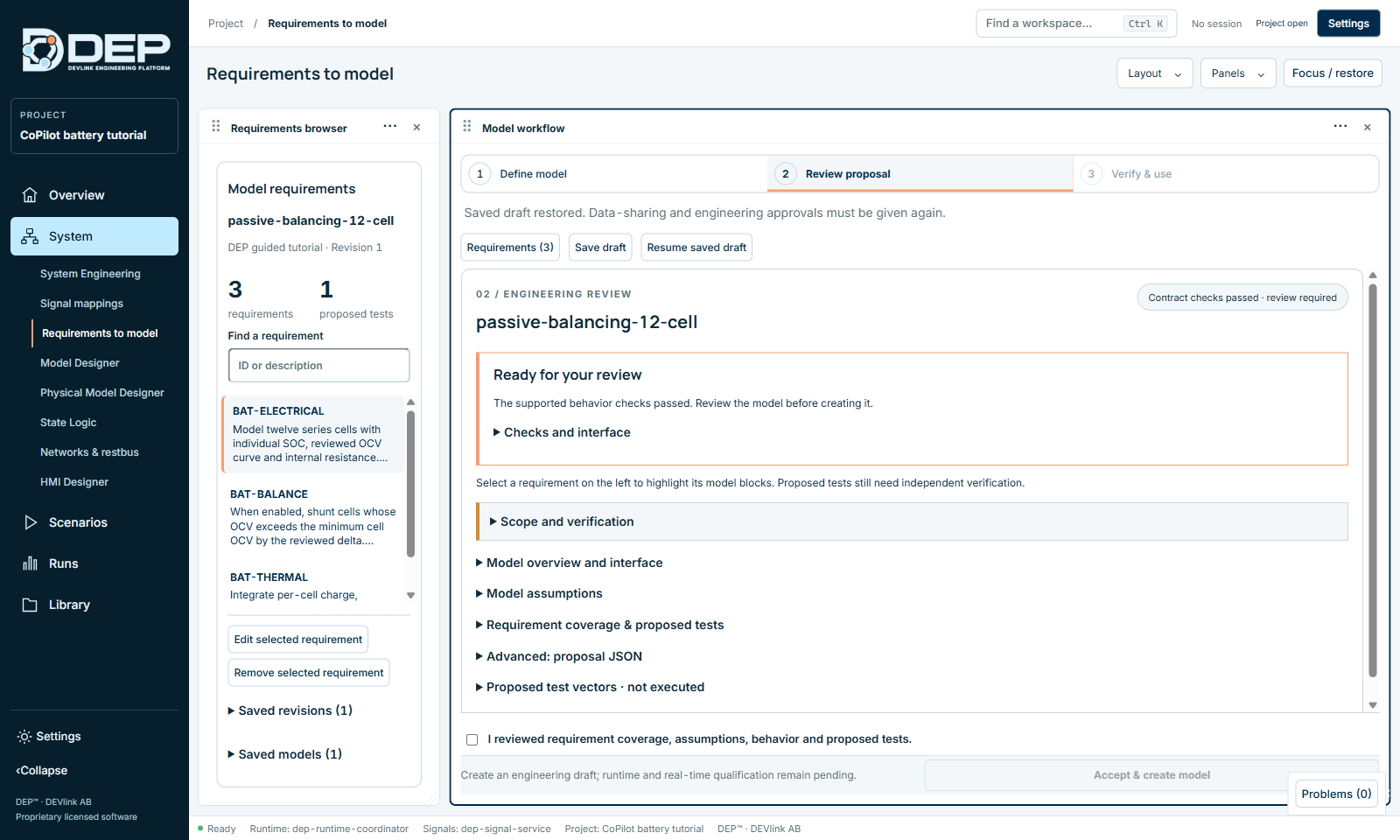
- Review the requirementsOpen System → Requirements to model and select Resume saved draft. The baseline passive-balancing-12-cell shows the three requirements, and the review step reports Contract checks passed · review required.
- Review the proposalExpand Model assumptions, Requirement coverage & proposed tests and Model overview and interface. Check the chemistry assumptions, cell count, capacity, initial SOC, voltage curve, resistance, balancing thresholds and thermal parameters. Select a requirement on the left to highlight its blocks.
- Create (optional)Tick I reviewed requirement coverage, assumptions, behavior and proposed tests. and select Accept & create model to generate a new engineering draft. Inspect it in Model Designer.
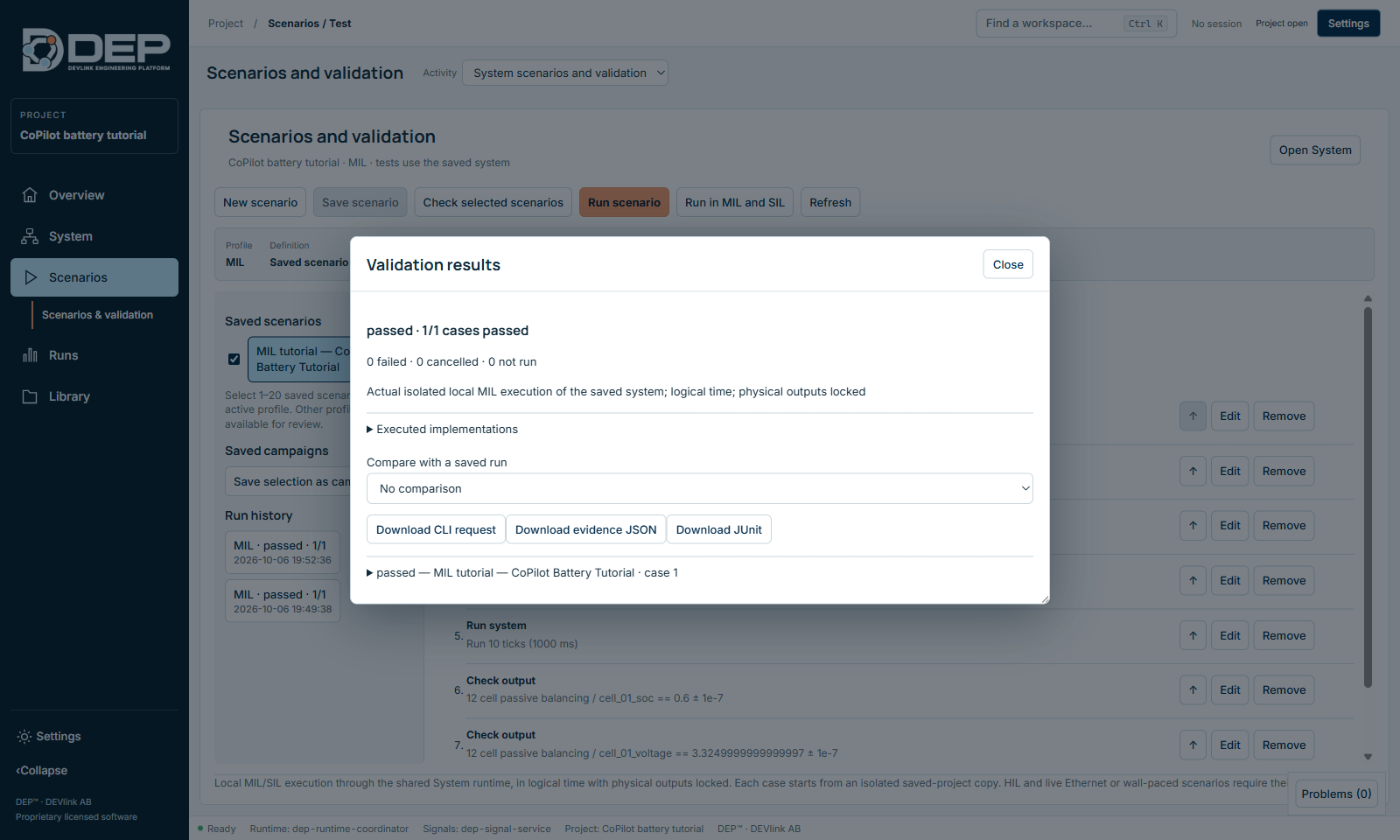
- Run the saved scenarioRun MIL tutorial — CoPilot Battery Tutorial. It sets requestedPackCurrent = 0, balancingEnable = 1, ambientTemperature = 298.15 K and reset = 0, runs 10 ticks (1 s), and checks cell 1: SOC 0.6, voltage 3.325 V and balance current 0. It passes.
- ReproduceReset and run again. The results must be identical.
To start the guided flow again from scratch on a fresh working copy, import CoPilot_Battery.requirements.json from the example folder with Import requirements…. Compare a changed calibration against independent charge and energy equations before you accept it. The parameter values are synthetic and illustrative.