

Build Your First System
In this tutorial you build a System from scratch: a Gain model feeding a First Order lag. You set an input, check and run the System, and read the response. It takes about 15 minutes. The values shown are what DEP produces for these settings.
What you learn
- Create a project and initialise its System.
- Add executable models from the catalogue.
- Connect an output port to an input port.
- Set an input value, then use Check, Run, Results and Live debug.
- Stop and release a session so that you can edit again.
1. Create the project
- New ProjectChoose File → New Project (Ctrl+N). In Create DEP Studio project, choose a folder you own, for example
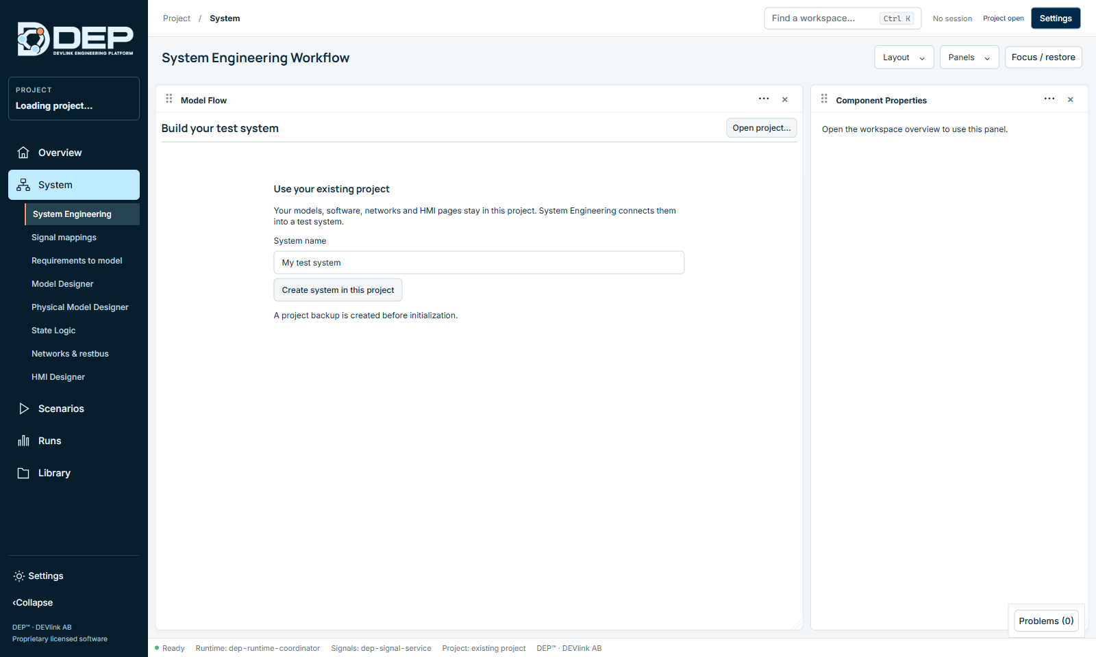
Documents\DEP Projects, and name the fileMy first system.rbsproj. Select Save. - Open System EngineeringSelect System → System Engineering. The panel shows Build your test system.
- Create the SystemType My first system in System name and select Create system in this project. DEP makes a project backup first.
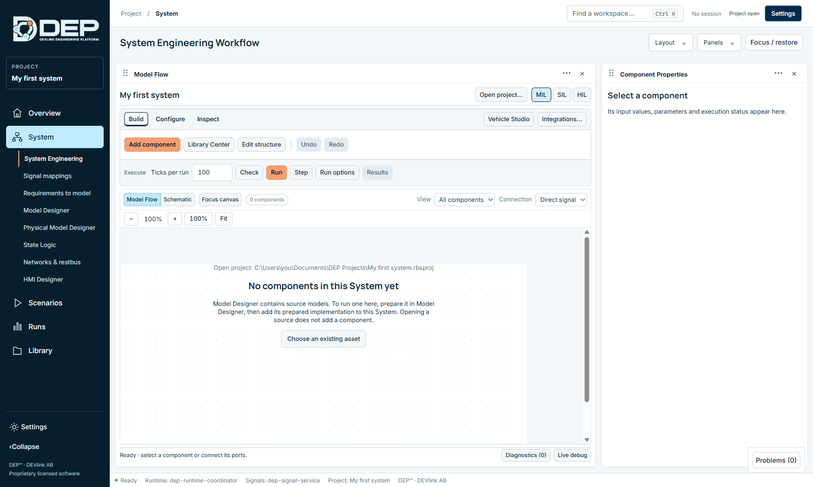
The canvas is now empty and shows 0 components. The profile buttons show MIL selected.
2. Add a Gain
- Open the catalogueSelect Add component in the Build toolbar.
- Find the modelThe dialog lists executable assets under the logical component types. Type gain in the search box Search models, software or networks.
- Add itSelect Gain (NativeModel · Executable model), then Add to system. The status line reports PASSED · add.
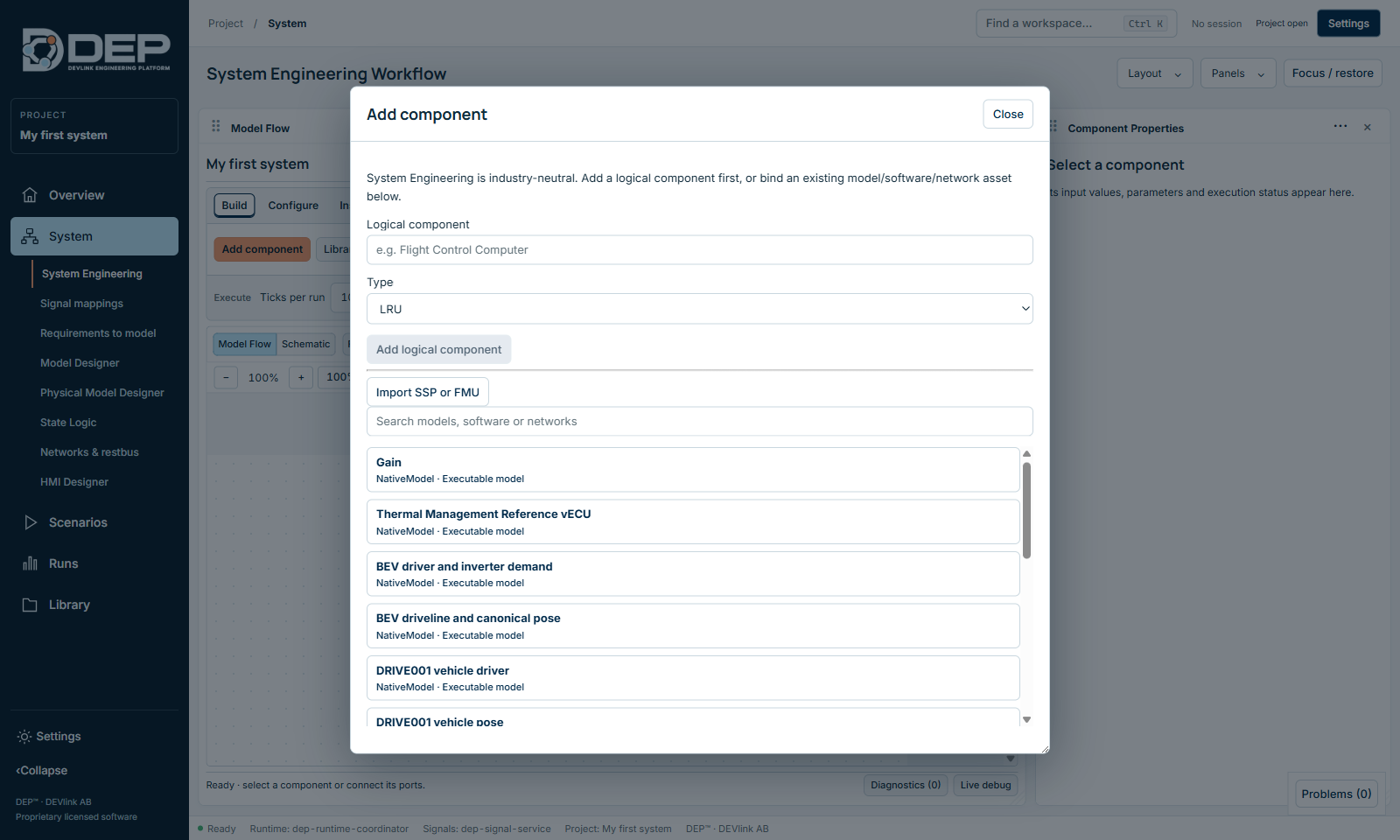
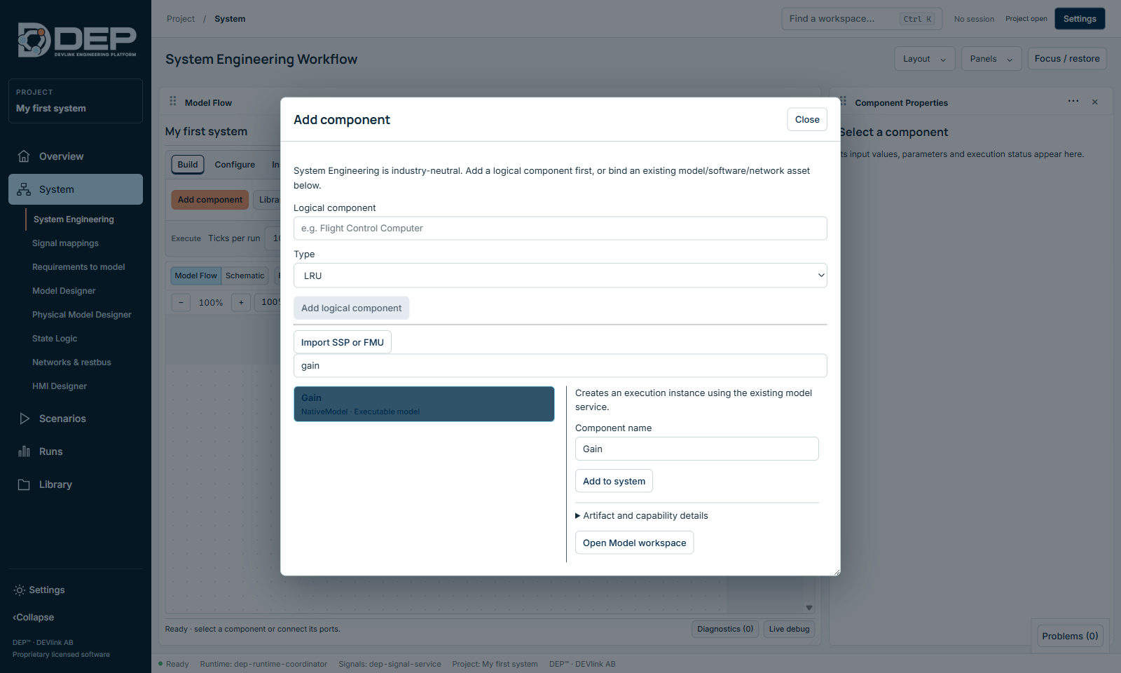
Logical component or executable asset? The upper part of the dialog, with Logical component, Type and Add logical component, adds a placeholder block, such as an ECU you will integrate later. A placeholder is Design only and does not execute. The list below it adds executable models. For this tutorial, use the list.
3. Add a First Order lag
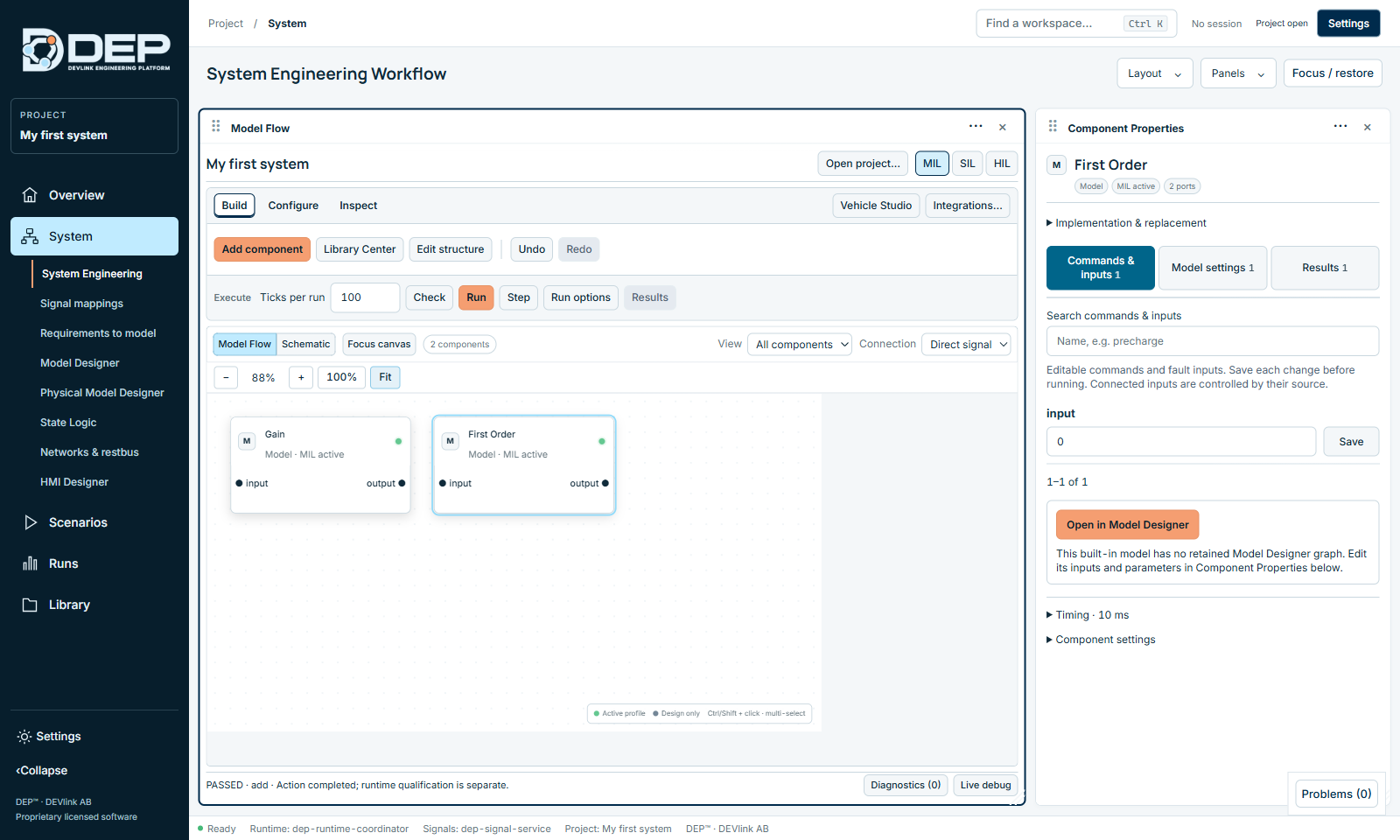
Select Add component again, search for first order, select First Order and Add to system. Close the dialog and select Fit to show both blocks.
4. Connect the components
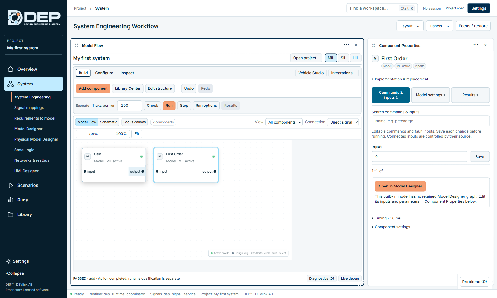
- Pick the sourceClick the output ● port of Gain.
- Pick the destinationClick the ● input port of First Order.
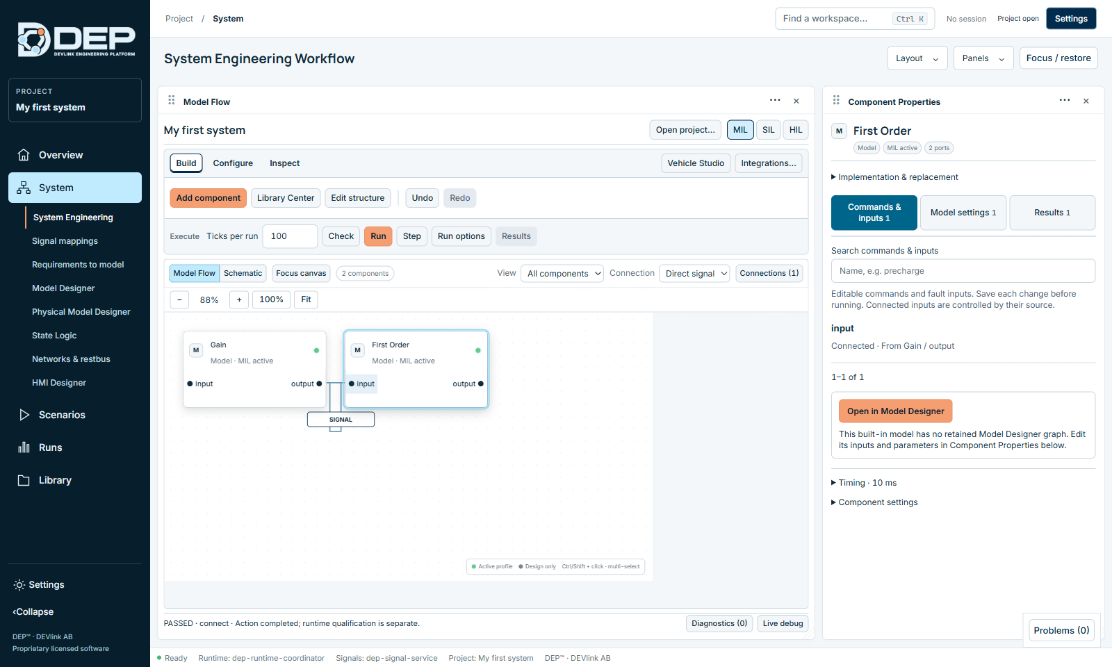
A line labelled SIGNAL appears, Connections (1) appears in the canvas toolbar, and the status line reports PASSED · connect. If you select First Order, its input now shows Connected · From Gain / output and can no longer be edited: a connected input always takes its value from its source.
To set a fixed value, do not connect anything to the input. Type the value in Component Properties instead. Connecting a component to its own input is not allowed.
5. Set the input value
- Select GainClick the Gain block. Component Properties opens on Commands & inputs.
- Enter 10In the input field type
10and select Save. The status line reports PASSED · value.
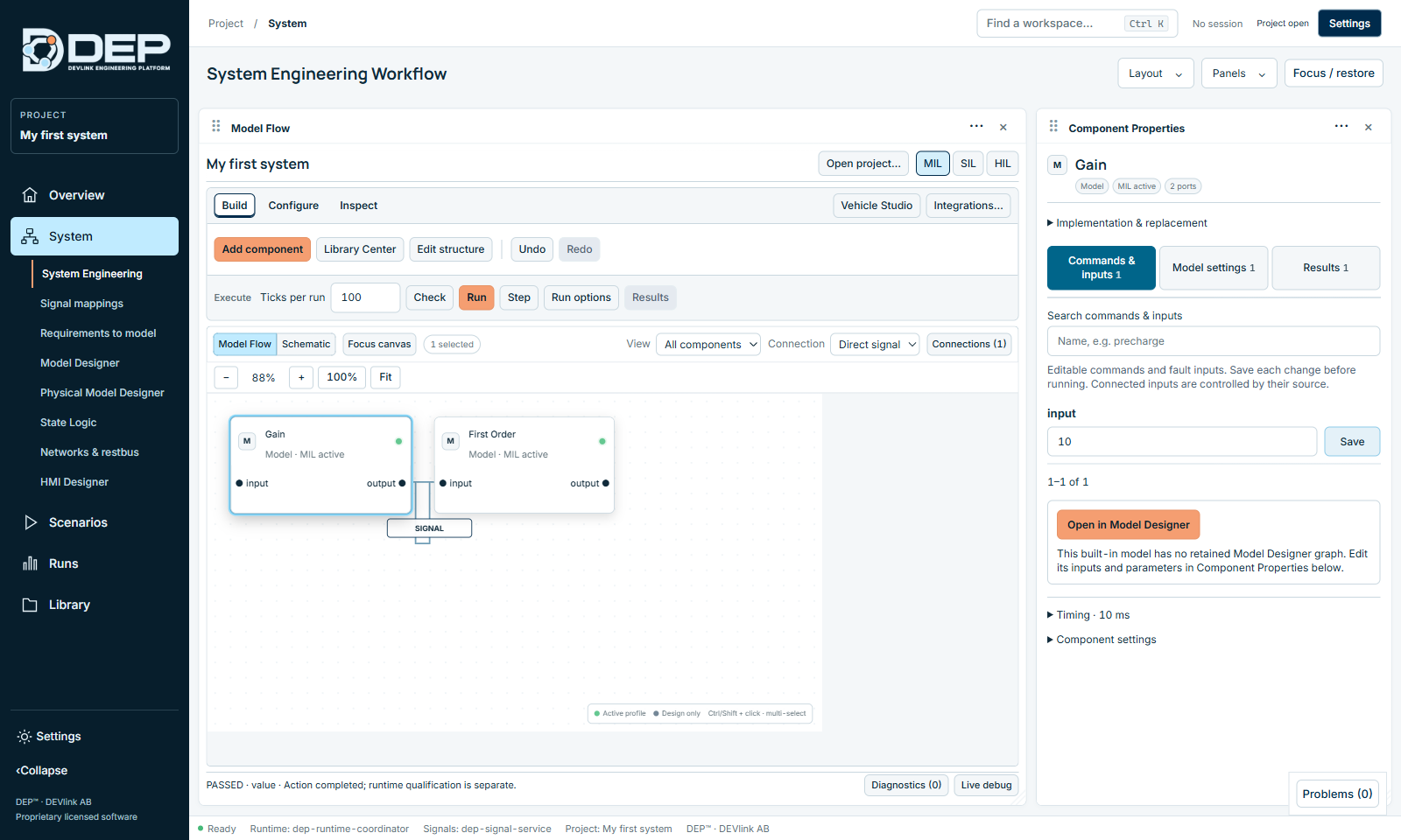
Model settings holds the parameters, here gain = 1. Results shows the last calculated outputs. Values must be saved before you run.
6. Check
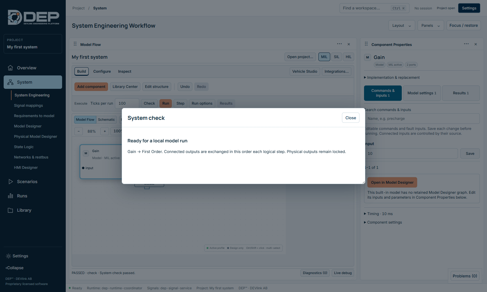
Select Check in the Execute bar. The System check sheet reports Ready for a local model run, the execution order Gain → First Order, and that physical outputs remain locked. Close the sheet.
7. Run and read the results
- RunKeep Ticks per run at 100 and select Run. With the default 10 ms step, 100 ticks are 1 s of logical time. The Live Session Debug panel opens and shows 100 / 100 committed ticks.
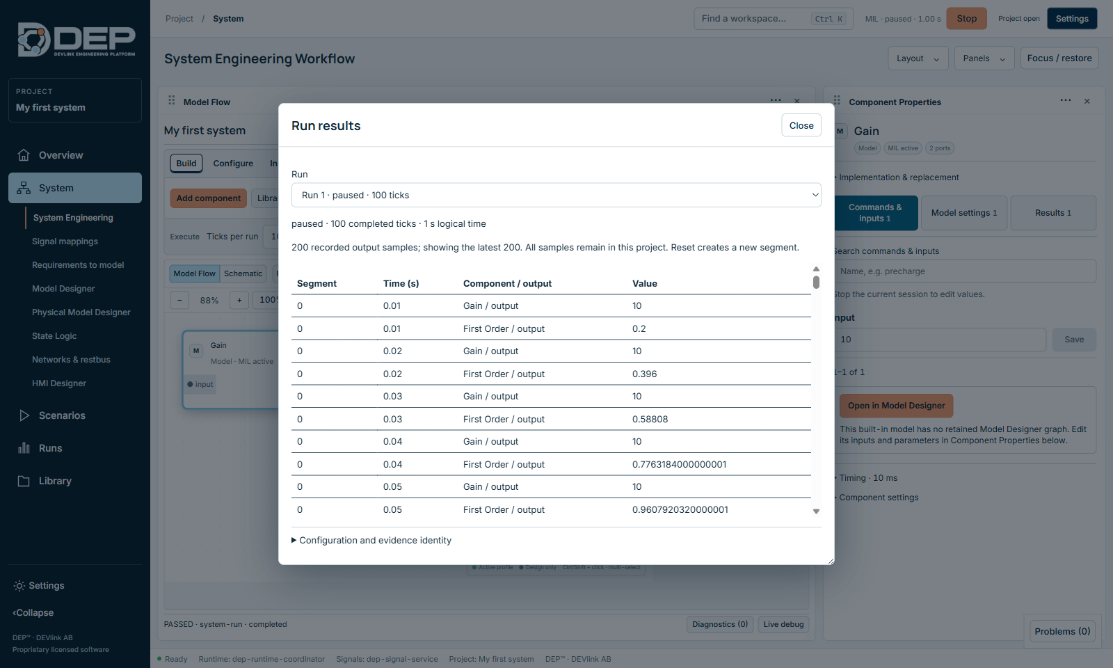
- ResultsClose Live Session Debug, then select Results. Run results lists every sample: Gain / output = 10 from the first tick, and First Order / output rising 0.2, 0.396, 0.588, … towards 10. It reaches about 8.7 after 1 s.
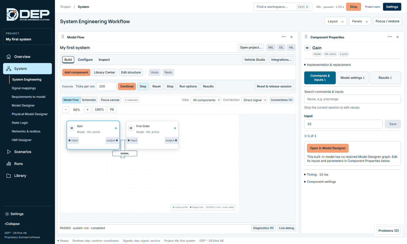
The session is now paused. The top bar shows MIL · paused · 1.00 s with a Stop button, and Run has become Continue. Select Continue to run 100 more ticks, or Step to advance one tick.
8. Stop, change and run again
- Release the sessionWhile a session exists, inputs are locked (Stop the current session to edit values.). Select Reset & release session in the Execute bar. The status line reports PASSED · release-session · stopped.
- Change somethingFor example, set Gain's gain in Model settings to 2 and save.
- Run againSelect Run. Gain now outputs 20, and the lag rises towards 20.
9. Save
Your changes are already stored in the project. Choose File → Save Project (Ctrl+S) to make sure every draft is written.
Next steps
- Turn this into an automated test: Scenarios, Campaigns and Evidence shows how to set the input, run 100 ticks and check that the lag output exceeds 8.
- Draw your own model instead of using a catalogue block: Model Designer.
- Learn every option of the canvas and inspector: System Engineering.
- Understand sessions, Step, Continue and Stop: Running MIL and SIL.