

First Session: Charge 20 → 80 %
This is the recommended first session with DEP. You open a ready-made charging System of five connected models and check it. You then run a complete DC charging session from 20 % to 80 % state of charge, watch it live, and confirm the safe stop. No charger, vehicle or extra software is needed. It takes about 30 minutes, most of it watching the session run.
What you need
- DEP installed (Install and Activate).
- The bundled example Editable battery charging session (
ChargeLink_MIL_Editable.rbsproj). - A folder where you can save your own copy.
The system you will run
The battery is a 100 Ah reference pack. The charger is limited to 150 A. The controller runs the session in four stages: Model initialization, Precharge, Energy transfer and Target and safe stop. There is no communication protocol in MIL: the stages come from the models' committed values.
1. Open the example and save a copy
- OpenOn the Overview, select Projects, then Open on Editable battery charging session.
- Save your copyChoose File → Save Project As... and save it in your own folder, for example
Documents\DEP Projects\My charging session.rbsproj. Never edit the original inside the DEP installation.
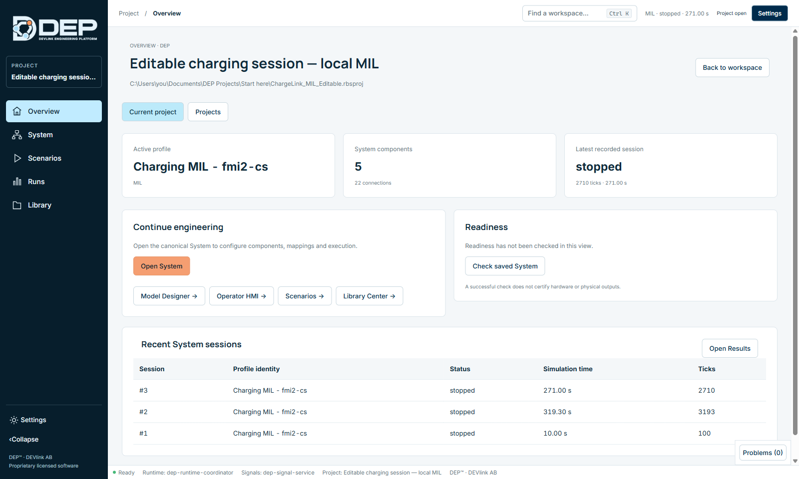
The Overview shows the active profile Charging MIL - fmi2-cs. The models run as FMI 2 co-simulation units. It also shows 5 components with 22 connections, and any earlier recorded sessions.
2. Inspect and check the System
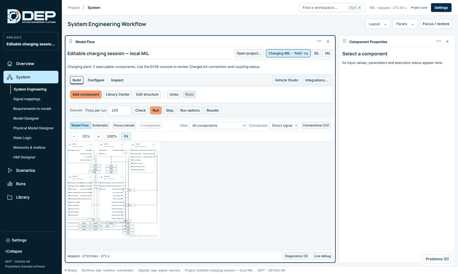
- Open the SystemSelect Open System, then Fit. You see battery, thermal, charger, interlock and controller, connected by 22 signals.
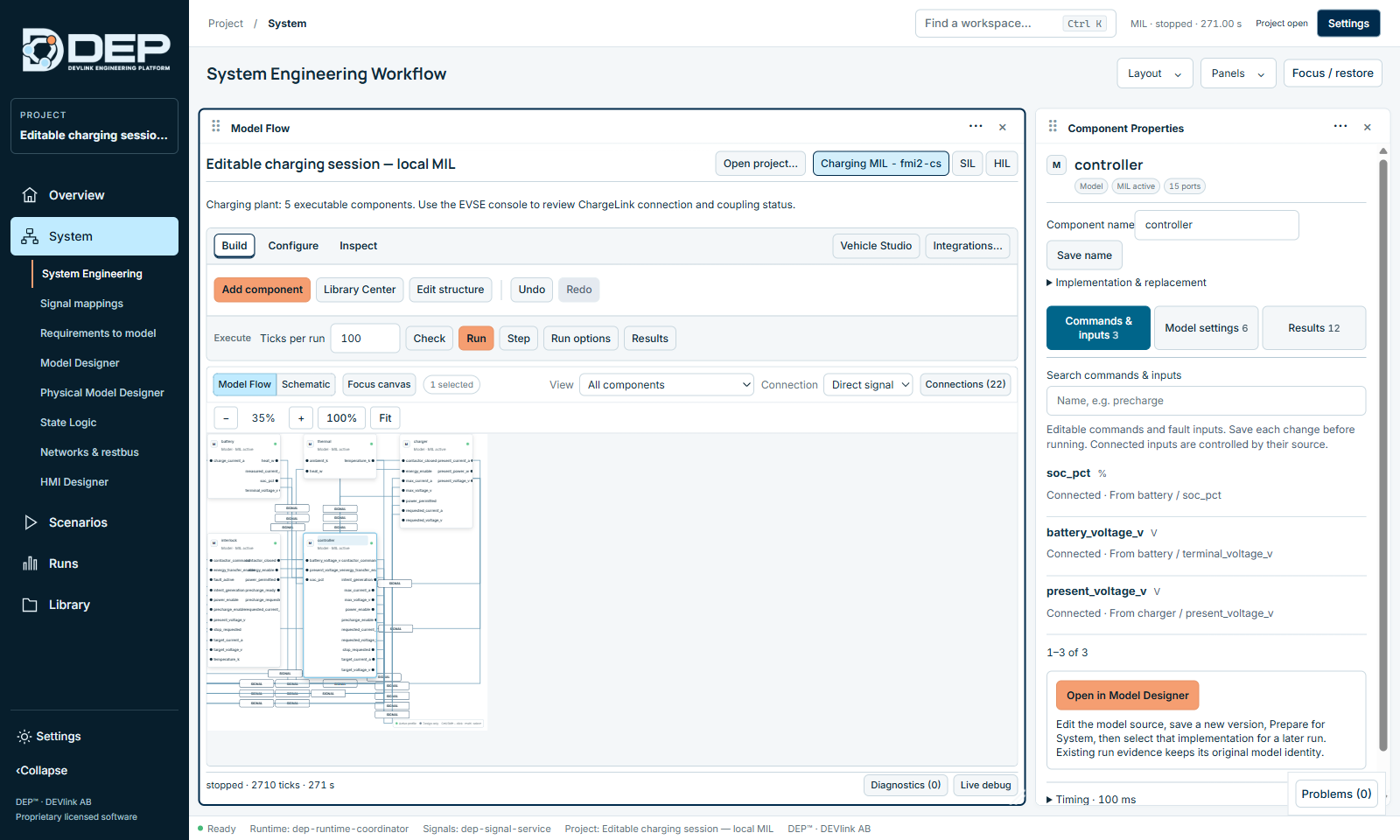
- Look at a componentSelect controller. Component Properties lists its inputs, model settings and latest results.
- CheckSelect Check. The sheet reports Ready for a local model run, and the status line reports PASSED · check · System check passed. Close the sheet.
3. Open the EVSE console
- Open the operator screenSelect Runs → Operator HMI. You can also use System → HMI Designer.
- Choose the consoleIn the activity selector at the top left, choose EVSE console.
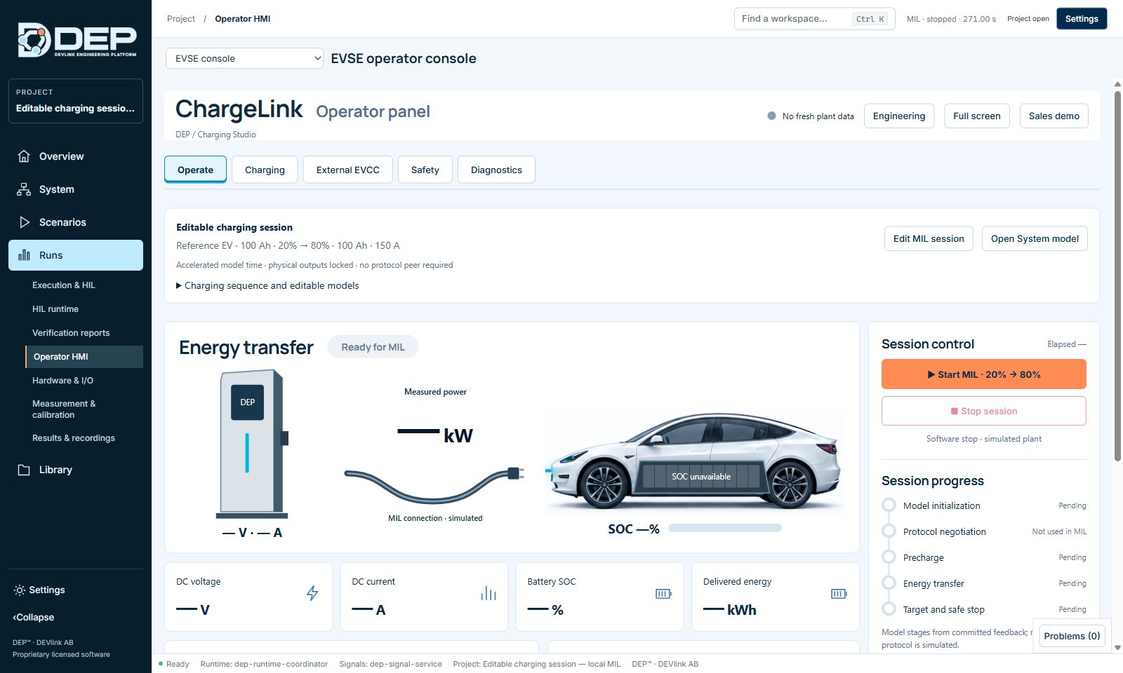
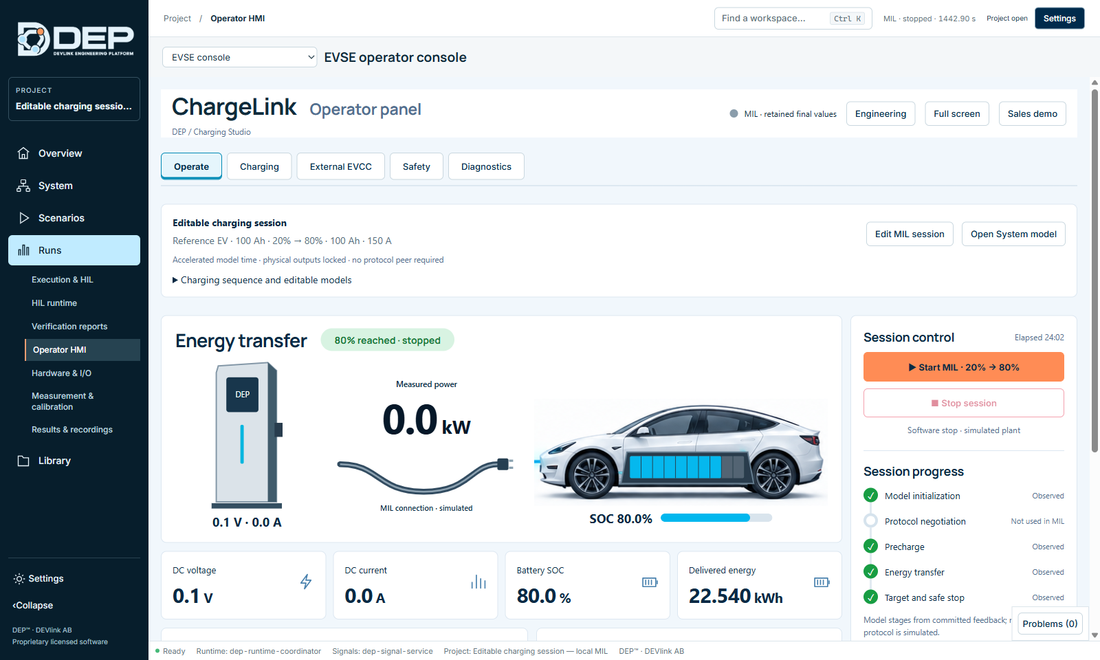
The ChargeLink Operator panel has the tabs Operate, Charging, External EVCC, Safety and Diagnostics. On Operate you see the session summary (Reference EV · 100 Ah · 20% → 80% · 100 Ah · 150 A), the energy-transfer graphic, four value cards, Session control and Session progress.
4. Review the session parameters (optional)
Select Edit MIL session to see the editable parameters:
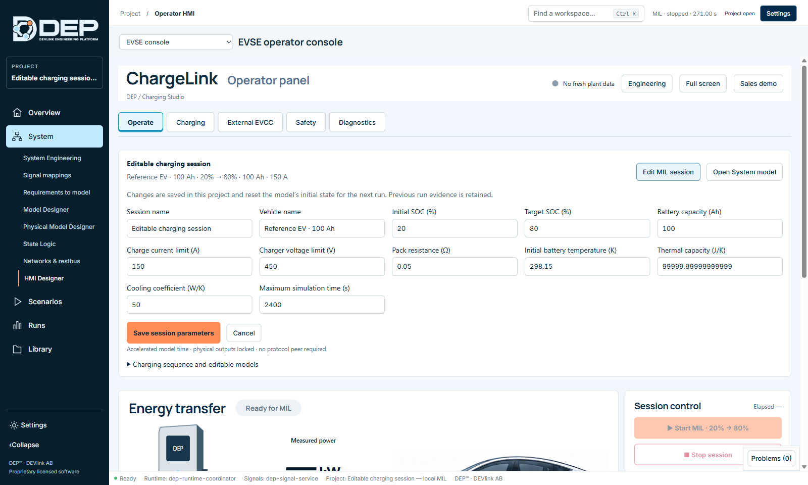
| Parameter | Meaning |
|---|---|
| Session name, Vehicle name | Labels shown in the console and the report. |
| Initial SOC (%), Target SOC (%) | Start and end of the charge, here 20 and 80. |
| Battery capacity (Ah) | Pack capacity, here 100. |
| Charge current limit (A), Charger voltage limit (V) | Charger limits. |
| Pack resistance (Ω) | Internal resistance; it determines voltage rise and heat. |
| Initial battery temperature (K), Thermal capacity (J/K), Cooling coefficient (W/K) | Thermal model. |
| Maximum simulation time (s) | Safety limit for the run. |
For this first run, keep the defaults and select Cancel. If you change values later, select Save session parameters. Saving resets the models' initial state for the next run, and earlier run evidence is kept. Change the parameters only while no session is running.
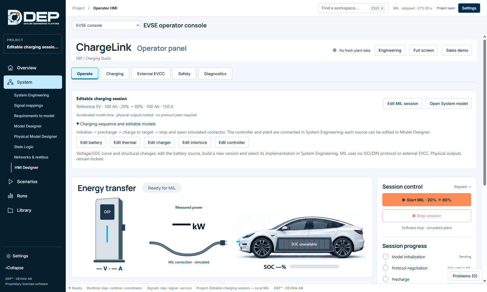
Expand Charging sequence and editable models to see the sequence (Initialize → precharge → charge to target → stop and open simulated contactor) and the buttons Edit battery, Edit thermal, Edit charger, Edit interlock and Edit controller. They open each model in Model Designer.
5. Start the charge
Select ▶ Start MIL · 20% → 80%. Within a few seconds:
- the status turns to charging, and the console header shows MIL · live model feedback;
- Model initialization and Precharge are ticked, and Energy transfer shows Active exchange;
- DC voltage rises to about 350 V at 150 A (about 52 kW), and SOC starts increasing;
- the top bar shows MIL · Running · … s with a Stop button.
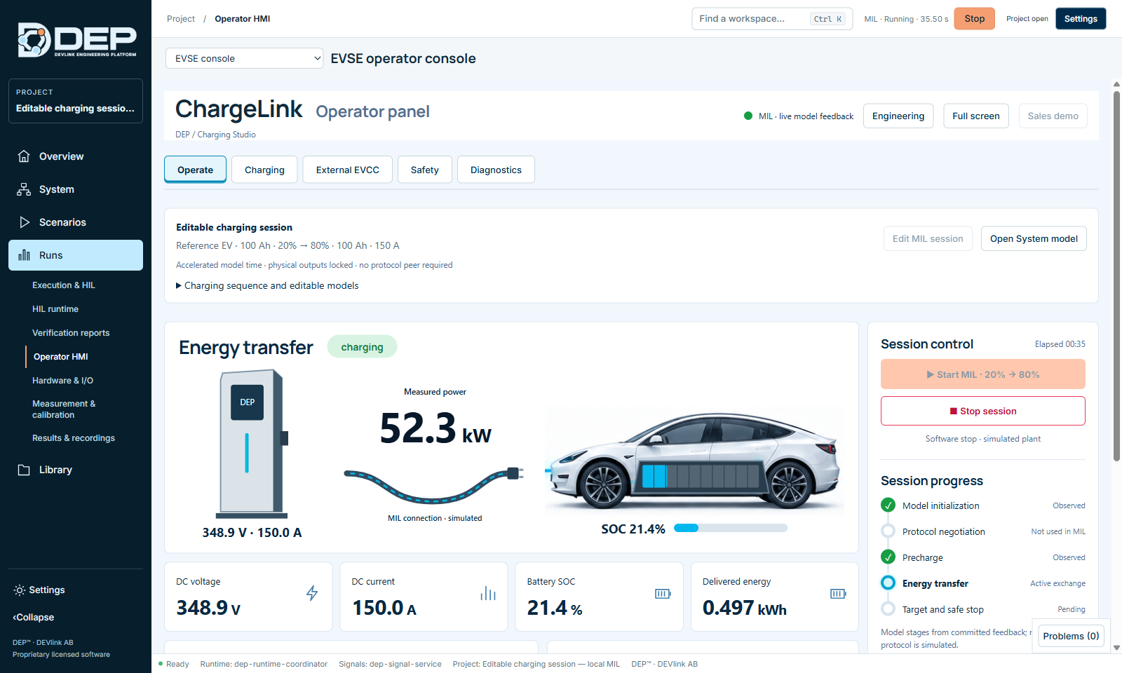
The session runs in accelerated model time. On a typical PC the full charge takes about 10 minutes of wall-clock time. The Elapsed counter shows model time.
6. Watch the values in System Engineering
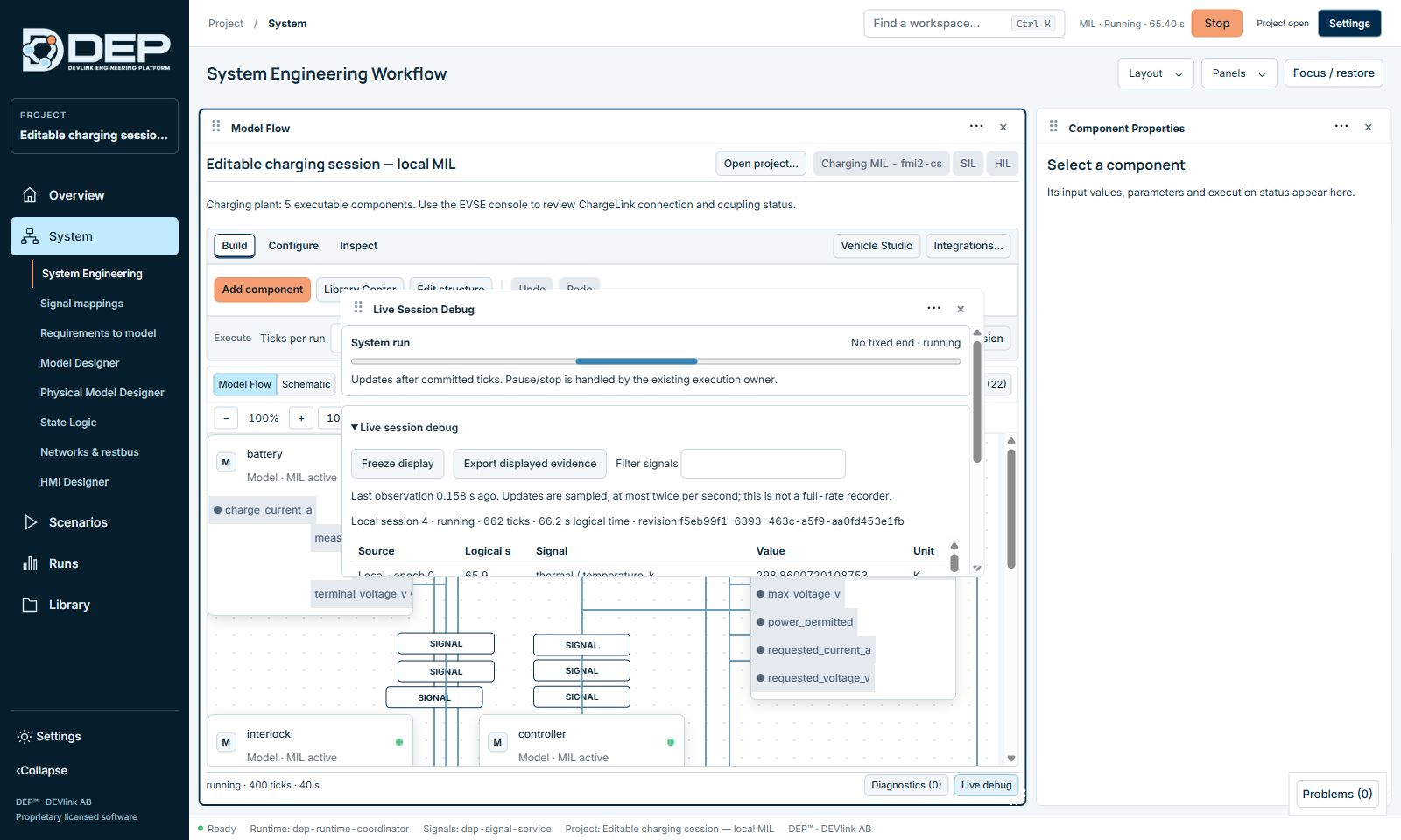
While the session runs, open System → System Engineering and select Live debug. The panel lists the committed values of every output, for example battery / soc_pct, charger / present_current_a and thermal / temperature_k, with logical time and unit. Select Freeze display to read a moment at leisure. Execution continues in the background.
Return to Runs → Operator HMI → EVSE console to follow the charge.
7. Reach the target and stop safely
When SOC reaches 80 %, the controller ends energy transfer, reduces the current to zero and opens the simulated contactor. The console then shows:
- 80% reached · stopped and the note ⓘ 80% SOC target reached;
- all four stages ticked as Observed;
- SOC 80.0 %, current 0.0 A, about 22.5 kWh delivered, and an elapsed model time of about 24 minutes;
- Plant feedback: Retained final values. The displayed values are the final committed values, not live values.
To end a session early, select ■ Stop session, or Stop in the top bar. Both are software stops of the simulated plant.
8. Export the report and save
- ExportSelect ▧ Export report at the bottom of the Operate tab (MIL numerical evidence available) and choose where to save the report.
- Save the projectFile → Save Project. The session is recorded and appears on the Overview under Recent System sessions.
- Reload to confirmOptional: close and reopen the project. Retained values are marked as stopped, not live.
Try next
- Change the target to 85 %: after the session has stopped, select Edit MIL session, set Target SOC (%) to 85, select Save session parameters and start again.
- Create the four standard charging test cases on the Charging tab and run them (Charging and the EVSE Console).
- Edit a model, for example the pack resistance in the battery, and see how voltage and temperature change (Model Designer).
- Build a System of your own: Build Your First System.