
System Engineering
System Engineering is the centre of DEP. Here you assemble the System from components, connect them, set their values, choose the execution profile and start runs. Open it with System → System Engineering, or with Open System on the Overview.
Layout of the workspace
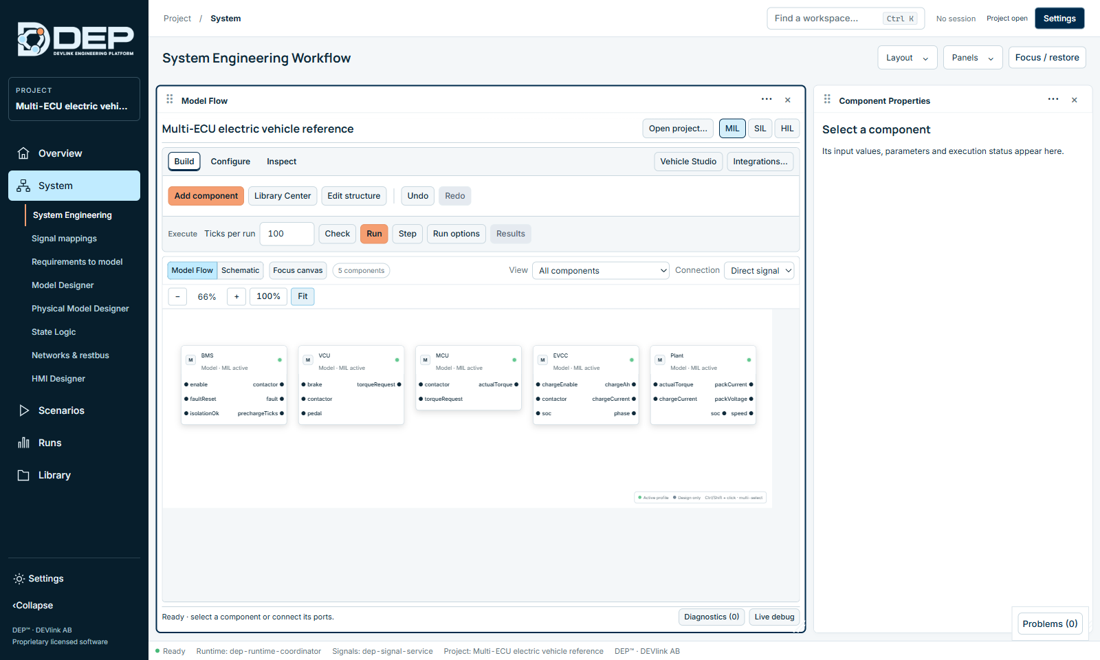
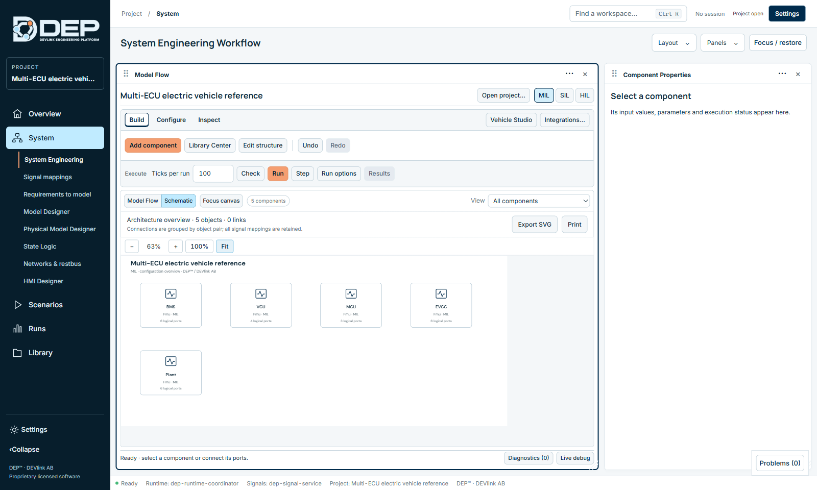
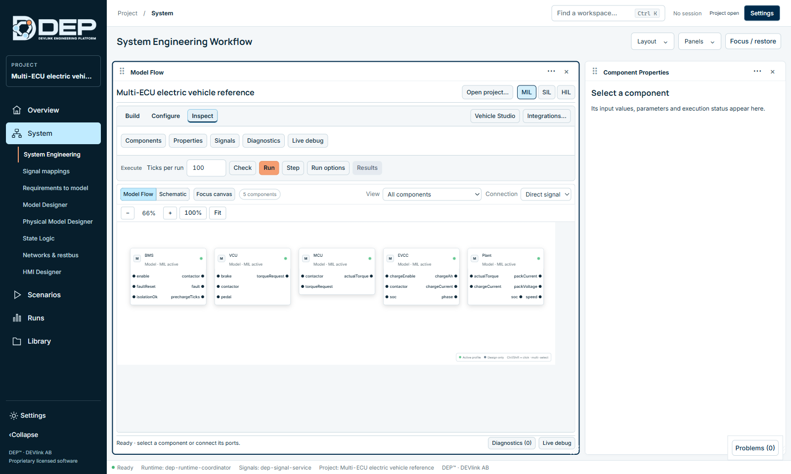
The workspace has two panels by default: Model Flow (the canvas and its toolbars) and Component Properties (the inspector). The Model Flow panel contains, from top to bottom:
- The System name, Open project… and the profile buttons (MIL SIL HIL, or the project's named profiles).
- The tabs Build, Configure and Inspect, with Vehicle Studio and Integrations… on the right.
- The toolbar of the selected tab.
- The Execute bar: Ticks per run, Check, Run, Step, Run options, Results.
- The canvas toolbar: Model Flow / Schematic, Focus canvas, the component count, View, Connection and zoom.
- The canvas.
- The status line with Diagnostics (n) and Live debug.
Choose the profile
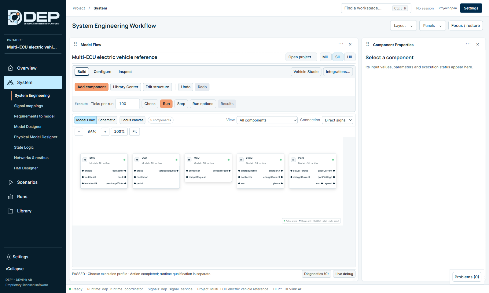
The profile buttons decide which implementation of each component runs. The active profile is highlighted. Each component shows its state, for example Model · MIL active or Model · SIL active. A dashed component is Design only in this profile and is excluded from execution.
- You cannot change the profile while a session or software process is active (
DEP-RUN-OWNER). Stop first. - If a component has no implementation for the selected profile, Check reports it. Assign one through Integrations… (see From MIL to SIL).
- HIL is selected here but executed through Runs → HIL runtime. See HIL Runtime.
Some projects define named profiles, for example Charging MIL - fmi2-cs. They behave the same way, and the name describes the implementation set.
Build tab
| Button | Action |
|---|---|
| Add component | Opens the component catalogue (below). |
| Library Center | Opens the reusable object library to add a reference model. See Library Center. |
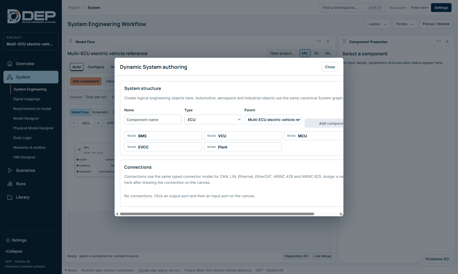
| Edit structure | Opens Dynamic System authoring: add logical components with a name, type and parent, and assign networks to connections. |
| Undo / Redo | Undo or redo structural changes. |
Add component
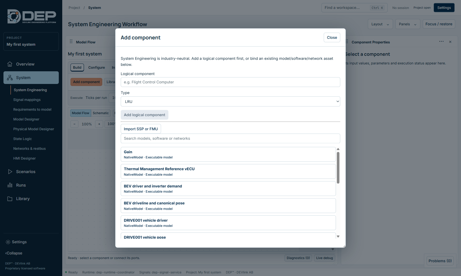
The dialog has two parts:
- Logical component: type a name, choose a Type (ECU, vECU, LRU, vLRU, PLC, Gateway, Sensor, Actuator, Model, Network, Subsystem or DUT) and select Add logical component. For a Network, also choose the protocol: CAN, CAN FD, LIN, Ethernet, EtherCAT, ARINC 429 or ARINC 825. A logical component is a design placeholder until you bind an implementation to it.
- Executable assets: the list of models and software already available in the project, each with a badge: Executable model, Composition · checked when added, or Design / integration required. Search with Search models, software or networks, select an entry, optionally type a Component name, and select Add to system.
- Import SSP or FMU imports a new package directly. See Software, FMI and SSP.
The catalogue of a new project contains DEP's built-in executable models, for example Gain, First Order, Threshold, Counter, Customer EV Longitudinal Plant, Thermal Management Reference vECU, BMS Reference vECU and the aerospace and drive references. Models you prepare in Model Designer appear here too.
The canvas
- Select: click a component. Use Ctrl/Shift+click to select several. The canvas toolbar shows n selected.
- Move: drag a component.
- Connect: click an output port (right side, output ●), then an input port (left side, ● input) of another component. Inputs and outputs can be connected only between different components.
- Zoom: − / + , the percentage buttons, Fit. Focus canvas hides the toolbars to give the canvas more room.
- View: All components or a single subsystem.
- Connection: Direct signal or a network. New connections use the selected network. Connections (n) lists them.
- Schematic: switches from the Model Flow layout to a schematic drawing of the same System.
- The legend at the bottom right explains the colours: Active profile, Design only.
Component Properties
Select a component to see its properties.
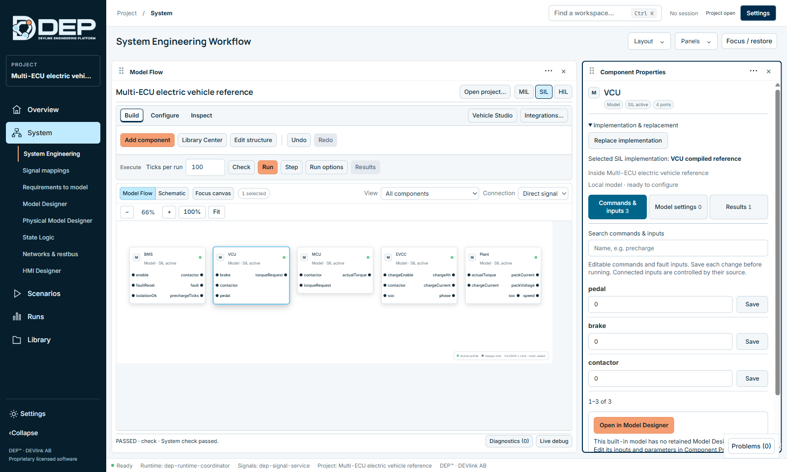
| Section | Contents |
|---|---|
| Header | Name, kind (for example Model), state (MIL active) and number of ports. |
| Implementation & replacement | The implementation selected for the active profile, and Replace implementation. |
| Commands & inputs | Editable input values and fault inputs. Each has its own Save. Connected inputs show their source instead. |
| Model settings | Parameters and initial conditions, for example gain. Save before running. |
| Results | Read-only outputs calculated by the last execution. |
| Open in Model Designer | Opens the model's source graph. Built-in models without a graph say so and are edited here instead. |
| Timing | Update every (ms): the component's period, a multiple of the base tick. Connected inputs hold the latest source value between updates. |
| Component settings | Include in this profile / Exclude from this profile, Open source workspace. |
| Application lifecycle | For software components: Check executable, Start application, Refresh application status, Stop application. |
Use the search box to find a value by name, for example precharge. Values cannot be edited while a session exists: Stop the current session to edit values.
Replace an implementation
- Expand Implementation & replacement and select Replace implementation.
- Choose the Replacement profile (MIL or SIL), then Choose artifact.
- Select Review replacement. DEP maps the ports. Use matching port names maps them automatically.
- Tick I reviewed every mapping… and select Apply reviewed replacement.
If the replacement cannot complete, DEP shows DEP-OBJ-REPLACEMENT and nothing is changed.
Configure tab
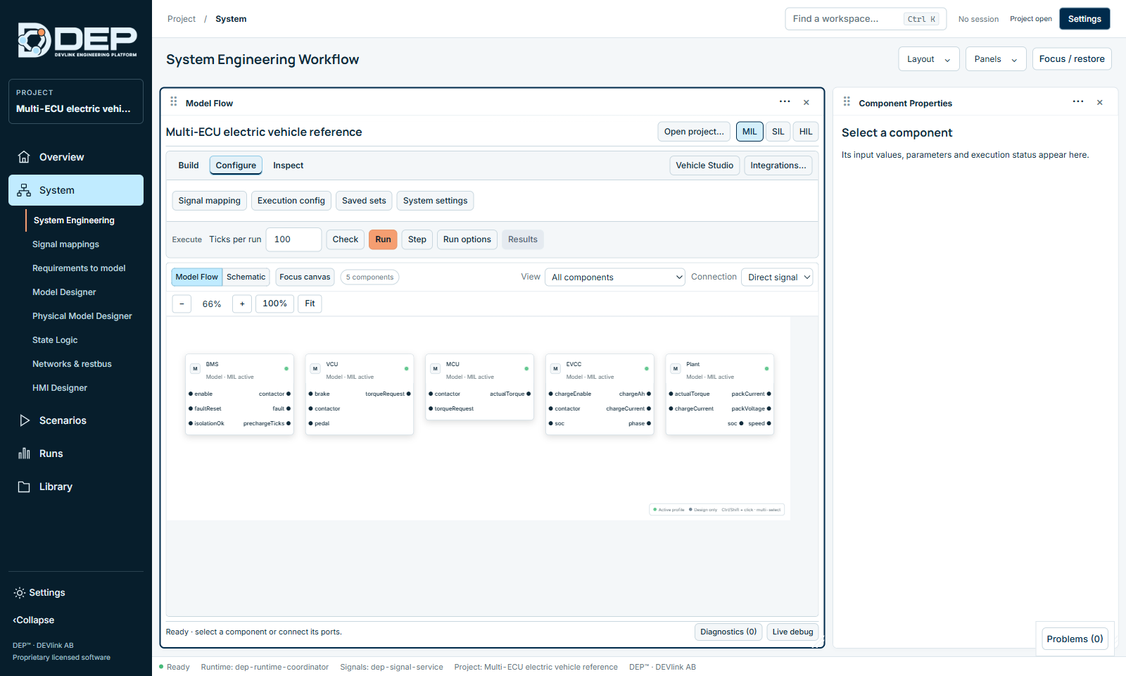
The Configure tab holds the settings that apply to the whole System:
- Signal mapping: the canonical signal and bus mapping matrix. See Signal Mappings.
- Execution config: the Deterministic Execution Configuration that DEP generates from the System. Use Generate execution configuration, or Regenerate from current System when it is marked STALE — System revision changed.
- Saved sets: saved parameter sets. Enter a Set name and select Save current configuration to store all current values. Apply a set later to restore them.
- System settings: base tick and other System-wide options.
Inspect tab
Components lists all components. Properties opens the inspector, Signals shows the canonical signals, Diagnostics lists findings, and Live debug opens the live session panel.
Subsystems
In Edit structure (Dynamic System authoring), add a component of type Subsystem. Then choose it as the Parent of other components. Use View above the canvas to show the whole System or one subsystem. Subsystems keep large Systems readable. They do not change execution.
Check
Check validates the saved System for the active profile and opens the System check sheet:
- Ready for a local model run lists the execution order, for example Gain → First Order. Connected outputs are exchanged in this order each logical step.
- System needs attention lists each problem with the component it belongs to. Fix the problems and check again.
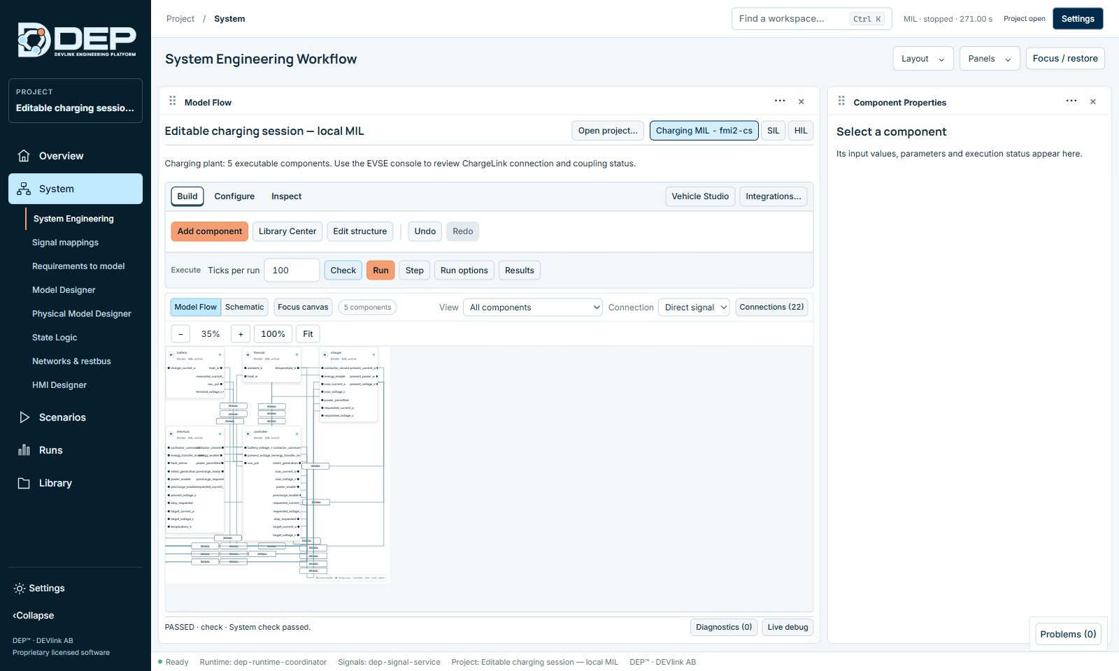
Common findings and their fixes are in Troubleshooting. Run checks again by itself. A passed check means the System is ready to run locally in logical time. It is not a certification.
Run options
| Option | Meaning |
|---|---|
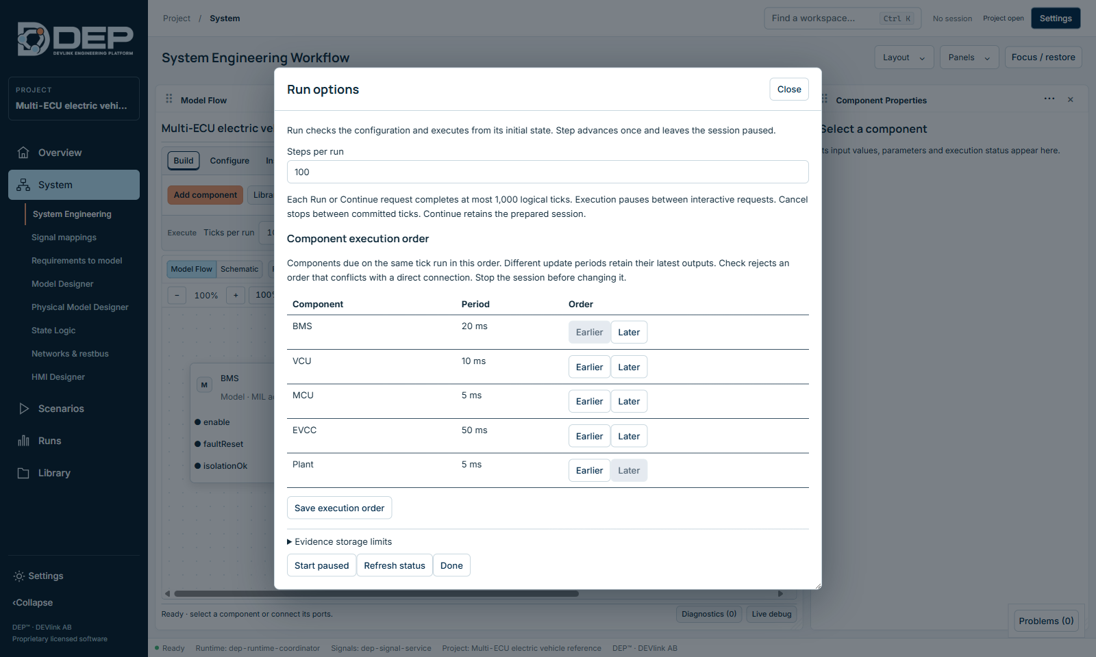
| Steps per run | Default batch size, the same as Ticks per run. Each Run or Continue completes at most 1,000 logical ticks. Cancel stops between committed ticks. |
| Component execution order | The table lists every component with its period, for example BMS 20 ms or MCU 5 ms. Components that are due on the same tick run in this order. Move a component with Earlier and Later, then select Save execution order. Check rejects an order that conflicts with a direct connection. Stop the session before changing the order. |
| Evidence storage limits | Maximum recorded rows and size for this project. When the limit is reached, recording stops with DEP-EVIDENCE-LIMIT. |
| Start paused | Create the session without running ticks, so you can step from the initial state. |
| Refresh status, Done | Update the status, or close the sheet. |
Running, stepping and results are covered in Running MIL and SIL.
Integrations…
| Section | What you can do |
|---|---|
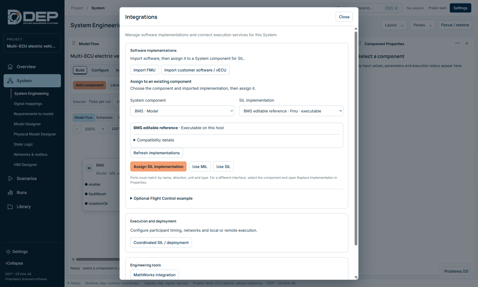
| Software implementations | Import FMU, Import customer software / vECU. Under Assign to an existing component, choose the System component and the SIL implementation (shown with its status, for example Executable on this host, and Compatibility details), then select Assign SIL implementation. Use MIL and Use SIL switch the profile, and Refresh implementations reloads the list. Ports must match by name, direction, unit and type. For a different interface, use Replace implementation in Component Properties. Optional Flight Control example adds a ready-made reference. |
| Execution and deployment | Coordinated SIL / deployment configures participant timing, networks and local or remote execution. See Coordinated SIL. |
| Engineering tools | MathWorks integration: Inspect SLX / MDL, Inventory project folder, Save editable DEP model, Build executable FMU for System. Only a restricted Simulink subset is supported. |
| Example projects and templates | Add reference templates to the current project, for example a flight-control reference, an aerospace MIL demo or charging reference models. Some templates require the MIL profile (DEP-CFG-PROFILE-MISMATCH). |
Vehicle Studio
Vehicle Studio connects the System to a separately installed 3D vehicle viewer (Godot based) for road and route demonstrations. You choose the installed application under Advanced, then Open & connect. Then you run the road scenario from Road & route. It is an optional visual companion and does not change the System's results.