

Model Designer
Model Designer is DEP's block-diagram editor. You draw a model from native blocks such as gains, integrators, switches and lookup tables, check it, and prepare it as an executable implementation the System can run. You can also export it as an FMU for other tools. Open it with System → Model Designer, or with Open in Model Designer in Component Properties.
The workspace
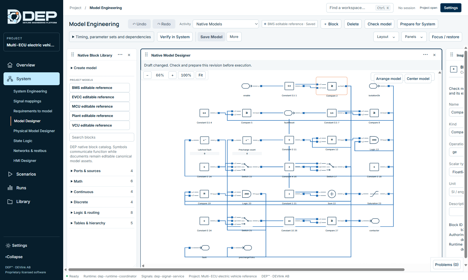
| Area | Contents |
|---|---|
| Toolbar | Undo, Redo, the Activity selector (Native Models, Software / FMI / model catalog, SSP Composition), the model badge (BMS editable reference · Saved), + Block, Delete, Check model, Prepare for System, Timing, parameter sets and dependencies, Verify in System, Save Model, More. |
| Native Block Library | Create model, the list of Project models, Search blocks and the block groups. |
| Native Model Designer | The canvas, with zoom, Fit, Arrange model and Center model, and a status line such as Draft changed. Check and prepare this revision before execution. |
| Inspector | Properties of the selected block. |
| Further panels | Project Explorer, Native DEP → FMU Export, Diagnostics. Show them from the Panels menu. |
Create or open a model
- Select a model under Project models to open it.
- Expand Create model, type a New native model name and create an empty model. Templates are also available: Create vehicle dynamics, Create aircraft dynamics, Create PMSM / inverter and Create mapped drive.
- From System Engineering, select a component and choose Open in Model Designer. Built-in models without a retained graph (for example Gain) explain that they are edited in Component Properties instead.
- From Library Center, create an editable copy of a reference model and select Open copy in Model Designer.
The block library
| Group | Blocks |
|---|---|
| Ports & sources | Input, Output, Constant, Parameter |
| Math | Gain, Sum, Product, Saturation, DeadZone, RateLimiter |
| Continuous | Integrator, ThresholdIntegrator, TransferFunction, StateSpace |
| Discrete | UnitDelay, Memory, Derivative, PID |
| Logic & routing | Switch, Relay, Compare, Logic, Mux, Demux, BusCreator, BusSelector |
| Tables & hierarchy | Lookup1D, Lookup2D, Subsystem, Scope, Terminator |
Expand a group and click a block to add it, or use + Block. Input and Output blocks become the model's ports when it is used in a System.
Edit on the canvas
- Connect: press a block's output port (right side). The canvas shows Connecting from <block> · select an input port. Then click an input port (left side) of another block. Port names such as u1, u2, sel and y are shown next to the ports.
- Context menu: right-click a block for Properties, Parameters, Duplicate and Delete.
- Select a block to edit it in the inspector. Move it by dragging, or with the arrow keys.
- Delete removes the selection. Ctrl+D duplicates it. Ctrl+Z and Ctrl+Y undo and redo.
- Arrange model lays the diagram out automatically. Center model centres it.
Block properties
The inspector shows Block properties for the selected block, for example Compare · editable DEP native block:
| Field | Meaning |
|---|---|
| Name | Display name on the canvas. |
| Kind | The block type. |
| Block parameters | Depend on the kind, for example Operation for Compare (ge, gt, le, lt, eq, ne), the gain value, saturation limits or table data. |
| Scalar type | Float64 — executable. Int64 and Boolean are authoring-only. |
| Unit | An SI or engineering unit. Units are checked when the model is connected in a System. |
| Sample time [s] | Optional block period, an integer multiple of the base sample time. |
| Description, Block ID | Documentation and identifier. |
Timing, parameter sets and dependencies
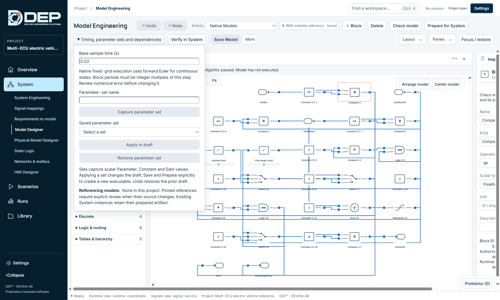
- Base sample time (s): the fixed step of the model, for example 0.02. Native fixed-grid execution uses forward Euler for continuous states. Block periods must be integer multiples of this step. Review the numerical error before you change it.
- Parameter sets: enter a Parameter-set name and select Capture parameter set. This saves the values of all scalar Parameter, Constant and Gain blocks. Choose a Saved parameter set and select Apply to draft to restore it, or Remove parameter set. Applying a set changes the draft only. Save and Prepare to create a new executable. Undo restores the previous draft.
- Referencing models: lists other models that use this one. Pinned references need an explicit review when their source changes. Existing System instances keep their prepared artifact.
Check, prepare and verify
- Save ModelThe badge changes from Unsaved to Saved. Ctrl+S saves the whole project.
- Check modelValidates the complete graph and its export capabilities, for example Rust compiler and FMI 2 CS eligibility passed. Model has not executed. Highlighted blocks show design issues: Correct the highlighted design issues before compiler checking or preparation.
- Prepare for SystemBuilds a new executable version of the model (Building executable model…). Existing System components keep using their previous version until you select the new one.
- Verify in SystemOpens Scenarios & validation so that you can run the System with the new version.
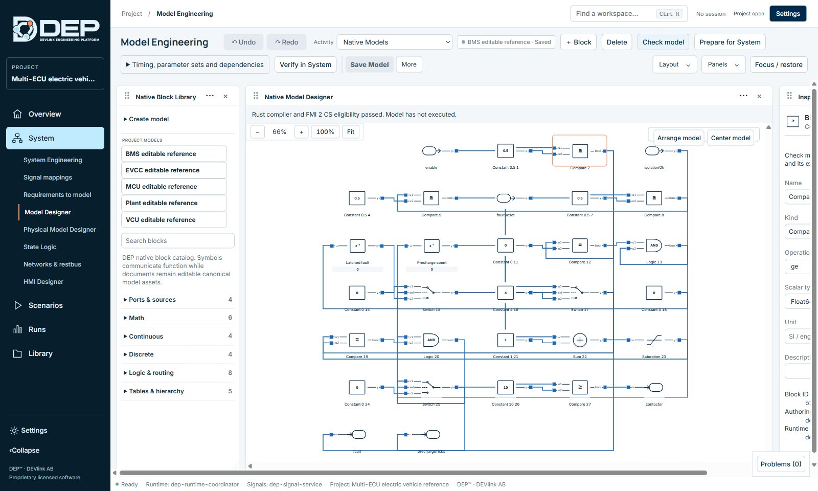
Check model and Prepare for System never change a running System. After preparing, select the new implementation in System Engineering (Implementation & replacement), press Check and run.
Versions
More → Rename model renames the model. Save as New Version keeps the current version and creates a new one (dialog Name new model version → Create version). Systems that pinned the old version keep it until you replace it. Save Project and Save As… are also in this menu.
Export an FMU
Open the Native DEP → FMU Export panel (Panels menu), choose a profile and select Export selected native model:
- FMI 2 Co-Simulation
- FMI 2 Model Exchange
- FMI 3 Co-Simulation
- FMI 3 Model Exchange
- FMI 3 Scheduled Execution
DEP builds the FMU (Building FMU…) and reports Exported · <path> · SHA-256 …, or Export failed · …. Export is fail-closed: a model that does not pass all checks is not exported. Specialised models (battery, drive, PMSM, aircraft, vehicle) are built through Prepare for System as FMI 2 co-simulation models instead.
Battery models
Battery models from the library, such as the cell-resolved electrothermal battery, open in a dedicated battery designer. There you can add and remove cells, set capacity and initial SOC, and set the pack structure under Pack settings: Series groups (S) and Parallel cells per group (P), for example a 6S2P pack of 12 cells. You can split the pack into named modules with Add module. The heading shows the result, for example Battery pack · 6S2P · 12 cells.